One Hundred Candles
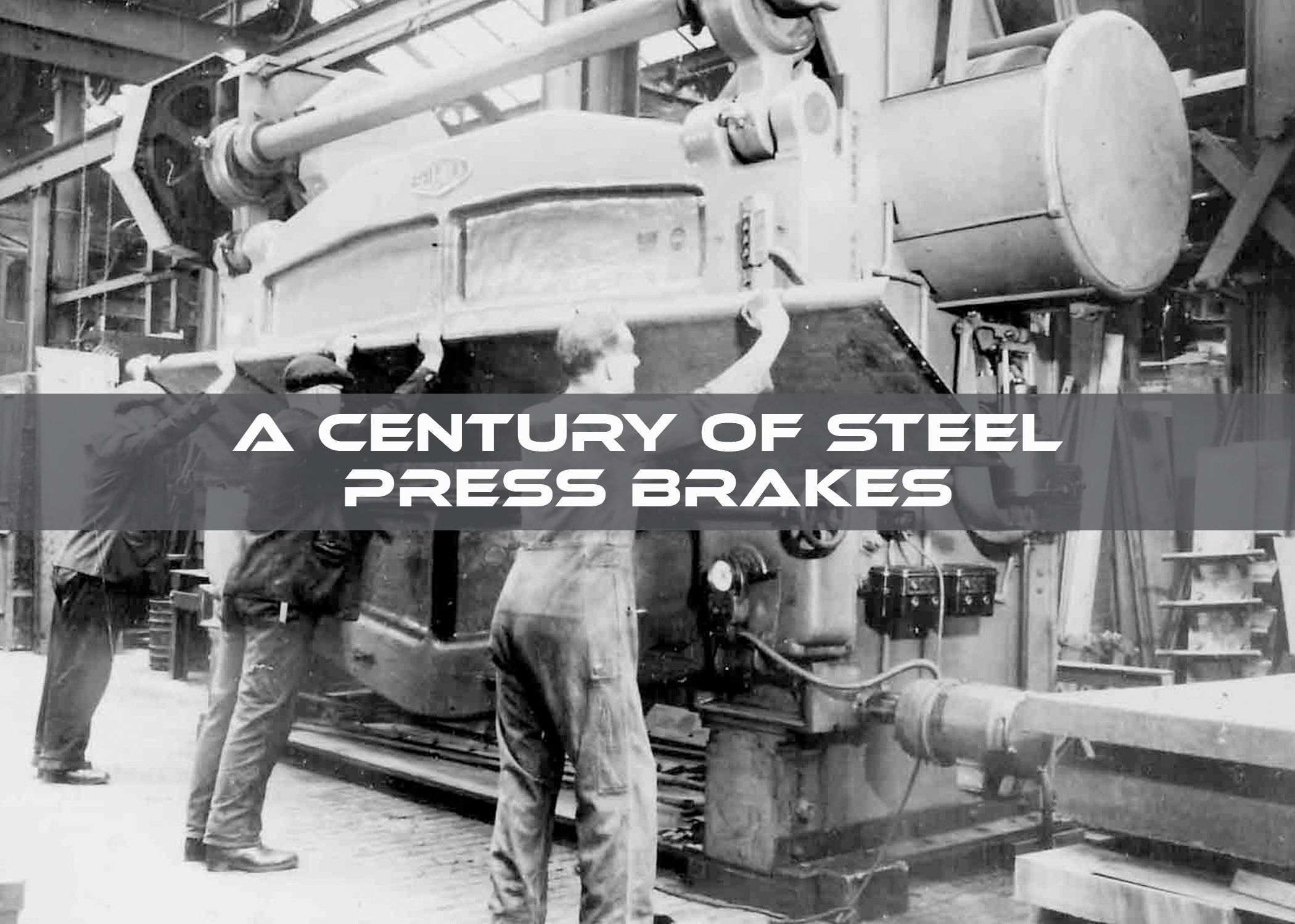
On July 30, 2024, steel press brakes, as we more-or-less know it today, celebrated its 100th birthday. It was on July 30, 1924, that inventor Robert T. Hazelton filed a patent in the United States for the first affordable, all-steel mechanical press brake, though it would take nearly three years for the patent to finally be issued on February 22, 1927.
While press brakes have come a long way in the last century, it can be informative to examine Hazelton’s patent and recognize just how groundbreaking his design was.
Dawn of the Press Brake
The term “press brake” and its general concept had been coined earlier, as is clear in Hazelton’s patent application:
“My invention relates to press brakes and power presses generally, which are used for bending and otherwise forming up of pieces of metal.
“It has been generally true of press brakes in the past, that their size and weight have been considerably out of line with the economy, or else they have not been of sufficient strength to withstand the strains attendant upon metal bending operations without distortion.”
Metal-bending brakes had been around since the early 1880s, when the cornice brake was patented in the U.S. More commonly referred to as a leaf brake or a straight brake today, the cornice brake was a manually operated machine that bent a piece of sheet metal along a straight line by clamping the metal in place and pivoting a bottom leaf of the machine upwards in an arc to bend the sheet to the required angle.
Powered presses, used for a variety of functions, including metal fabrication, had been around nearly a century longer––Joseph Bramah developed the first hydraulic press in England near the end of the 1700s. Though hydraulic press brakes wouldn’t begin to come on the scene until World War II, when U.S. companies began to look for ways to advance America’s war effort, the notion of powering a bending brake in some fashion was being developed in the early 20th century.
Better than Cast Iron
Hazelton’s reference to “press brakes in the past,” indicates that previous machines were either too large and heavy to be commercially viable (“their size and weight have been considerably out of line with the economy”) or were constructed in a way that was too flimsy to hold up to the needed operations (“they have not been of sufficient strength to withstand the strains attendant upon metal bending operations without distortion”).
That both categories of machines likely refer to press brakes that were constructed of cast iron, which Hazelton proposed to replace with steel, can be seen by the next section of his patent application: “It is the primary object of my invention to provide a press brake which is formed of steel, thereby possessing greater strength to withstand strains than prior structures of cast iron, and an attendant object has been to provide a machine of minimum practical weight, with all the strength and power that maximum demands could place upon it.”
While both cast iron and carbon steel have a tiny percentage of carbon in the mix, steel is considerably tougher. Cast iron is extremely hard, but is also very brittle, meaning that it can break when put under excessive pressure, something that is less than desirable in a press brake. Compared to cast iron, steel has both greater tensile strength (the maximum amount of stress a material can withstand before breaking) and yield strength (the minimum amount of force that can cause permanent deformation). Hazelton’s steel brake could withstand forces that might cause components of the earlier press brakes to fail.
Deflect Much?
Some beginning metal fabrication workers may assume that our understanding of the principle of deflection and how it affects both machine and workpiece is a more recent development, but both Leonardo da Vinci (1452 – 1519) and Galileo Galilei (1564 – 1642) were working on theories of deflection based on their own observations. In 1750, the Euler–Bernoulli beam theory was published, giving the mathematical equation that shows the relationship between a load applied to a beam and the deflection that occurs in the beam. Deflection theory was in full use by engineers by the end of the 19th century, being considered in the construction of suspension bridges, Ferris wheels, and even the Eiffel Tower.
Hazelton understood the problems deflection caused in the existing press brakes of his day, so his patent pointed out that “It is my object to provide for a ram and bed so formed and supported and operated that deflection under load is greatly reduced over machines of like type in use.”
Size (of Workpiece) Matters
Being constrained by the distance between housings was an issue quickly being recognized in that early press brake era, and Hazelton proposed a solution. “It is my object to so arrange for the support and operation of the ram and bed,” he wrote, “and for their relation to the housings, to permit of open throated housings, so that the effective length of the ram and bed is as great as the outside distance between the housings.
“Also in this connection it is my object to provide for full clearance between the housings so that work can be passed through between them.”
Watching Weight
Hazelton’s new design was heavily focused on making his press brake much lighter than previous models, as can be seen by these excerpts from his patent application:
“The construction of my machine is such that the heavy top member connecting the housings, from which in former machines the thrust on the ram was taken up, is eliminated thereby greatly cutting down weight, and head room.
“Instead of this top member, I take the load of the ram on bearings located in the housings themselves and apply the force to the ram at the ends, thereby clearing away a great deal of extra mechanism found in devices of the past, and obtaining greater strength and rigidity. Preferably I form the ram with greater height between the housings than at the point of application of force, thereby overcoming tendency to bending of the ram between its ends….
“In forming the housings, of which there are two, I provide for each housing a pair of large heavy steel plates… of sufficient width to withstand the tremendous strains thereon, and along the front of the pairs of plates I secure firmly in place by pinning, welding, riveting or bolting, the cast steel pillars… Thus the standards are hollow except at the front where the entire face is practically a single piece of solid steel. I have indicated metal plates… closing the housings along the back and top. These plates are firmly riveted or welded into place to hold the plates… in their correctly spaced relation and to strengthen the assembly. It may be observed that by this construction I have provided for housings which are lighter than the tremendous A-castings of the past, and possess greater strength, and in which solid steel is provided where necessary and omitted where not necessary.”
A More Robust Design
Hazelton was determined to make his press brake not only lighter but also sturdier: “The housings are connected together across the top by an L-shaped metal plate… which serves as a spacer and also takes up twisting strains in two directions….
“The result of the structure described, is to provide a very stiff structure, protected from twisting strains by means of the angle bars, more practical and economical than cast steel structures in which the reinforcing webs are integral, and a considerable advance in machine tool construction in the particular class in question….
“At the same time the internal height of the ram provides against the bending thereof under strains, without calling upon the general framework of the machine to provide for this….
“The provision of the eccentric devices between the housing forming plates is so rigid a structure, that no strains to be encountered in the line of work of such machines, can
have any effect upon it….
“[T]he depth of the bed… provides against distortion by bending, using the housings for the reception of the direct force applied by the eccentric devices.”
An Eye to Economy
Making a quality press brake that was easier on the bank accounts of early 20th century fabricators was also a concern of Hazelton’s: “The distribution of metal in the ram thus saves expense while providing a very stiff and rigid structure along the exact lines wherein this is desired, and not elsewhere….
“Furthermore… the structure is economical and much lighter than prior constructions in which the bending strains on the ram, and the thrust encountered along the lines of application of force, all had to be met by the top cross members of the framework of the press brake machine.”
Other Press Brake Improvements
The revolutionary new press brake designed by Robert T. Hazelton included other innovations, such as:
- Ease of Shipping. “My construction adapts itself most excellently to shipping in sections, and setting up in the shop of the customer and it has been one of my objects to so construct the machine that it is self-aligning in being set up, and in which the mechanism, being located in the housings, is shipped completely installed.”
- Safety. “I have improved upon the ram raising and lowering devices, and their adjustment, and by locating the working line of the machine well in advance of the mechanical parts as well as below them, I provide a greater factor of safety than has hitherto been found in machines of the type in question.”
The Press Brake Century
The design of press brakes over the last 100 years has progressed light years beyond Hazelton’s flywheel-powered machine, moving through different power sources: mechanical, hydraulic, electric, and servo hybrid. The accuracy of measuring devices and controls that are available today would have astounded Hazelton and his peers. The modern fabricator has much to be grateful for when comparing even the simplest machines on his shop floor to what was available a century ago.
Still, every press brake designer through the years built on what had come before, and the innovations proposed by Robert T. Hazelton for his “press brake which is formed of steel” set the stage for all the brakes of yesteryear and will continue to influence all the yet unimagined metal bending machines in the fabrication industry’s future.
