


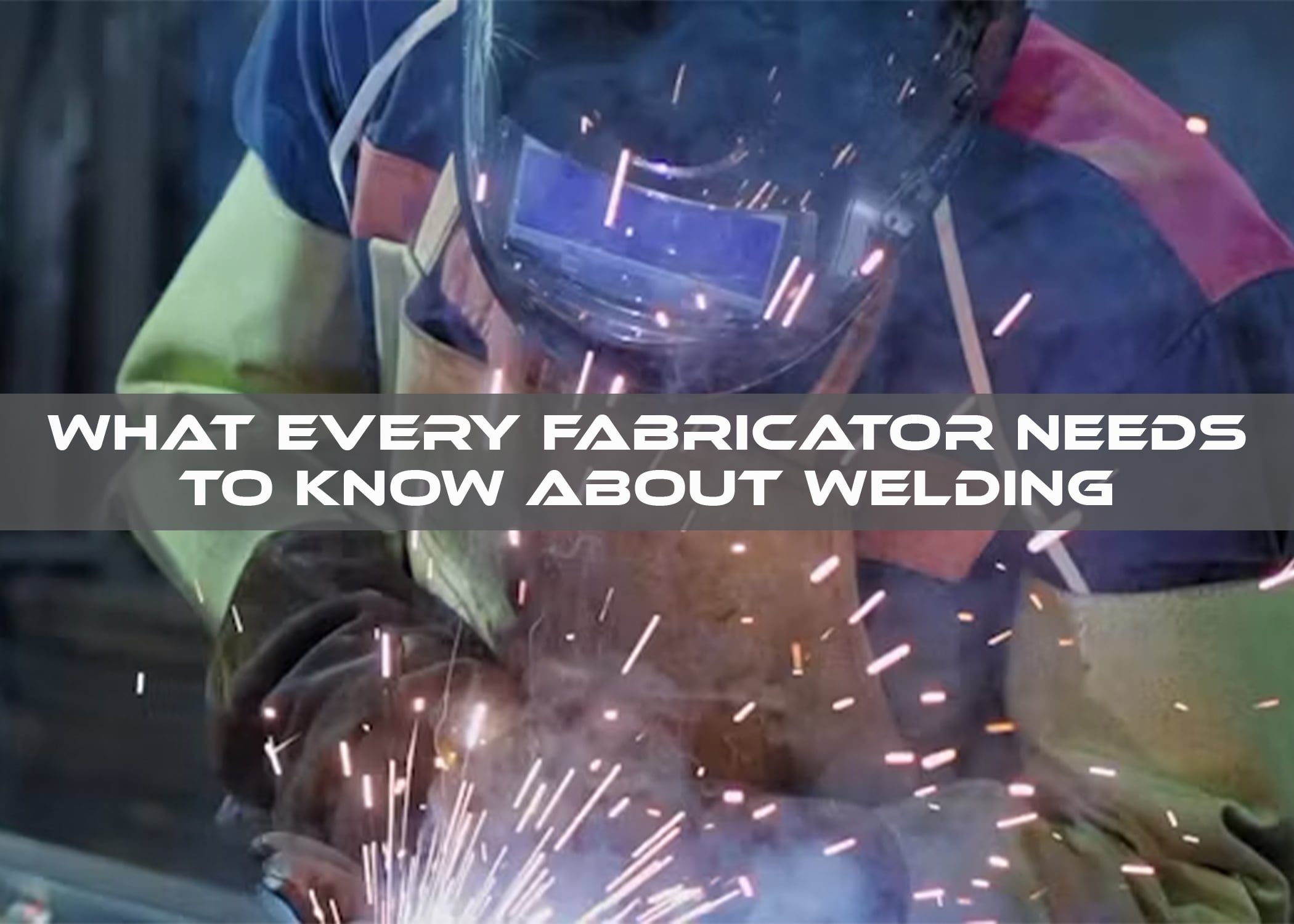
In almost any metal fabrication shop, an invisible line divides the cutting table from the welding booth. A fabricator spends their day measuring, shearing, laser-cutting, notching, and bending raw stock into precise components. A welder then receives those loose parts and fuses them into a single, cohesive assembly. Because these responsibilities are often divided between different workers or departments, it is easy for a non-welding fabricator to assume their job ends the moment a part matches the blueprint dimensions.
In reality, welding is not merely a mechanical joining method; it is an intense thermal and metallurgical event. How a part is cut, deburred, bent, and fitted directly dictates whether a welder can create a structurally sound and visually clean joint. By gaining a deeper understanding of the mechanics behind the arc, fabricators can bridge the gap between cutting raw steel and creating high-quality finished assemblies.
Thermal Distortion and Metal Movement
The most critical physical concept a non-welding fabricator must master is that metal expands dramatically when heated and contracts as it cools. Arc welding introduces localized temperatures that easily exceed 2,500 degrees Fahrenheit. As the molten weld pool freezes and cools back down to room temperature, it shrinks in volume, exerting massive mechanical forces on the surrounding, cooler metal. If a fabricator does not anticipate this thermal pull, an assembly that sat perfectly square on the layout table will warp and twist out of tolerance once the welding is complete.
This shrinkage manifests in three distinct ways across a joint. Transverse shrinkage pulls the adjacent metal plates inward, perpendicular to the weld line, shortening the overall width of the assembly. Longitudinal shrinkage causes the weld bead to contract along its length, which often bows long structural channels or tubing into a curve.
Finally, angular distortion occurs when fillet welds pull flange plates toward the side containing the weld pool, quickly turning what should be a sharp 90-degree corner into an acute 87-degree angle. Fabricators can counteract these forces before a torch is ever struck by presetting parts slightly out of square, clamping components back-to-back, or incorporating mechanical interlocking tabs that physically resist thermal pull.
Tolerances, Fit-Up, and the High Cost of Gaps
A common misconception on the shop floor is that a welding torch acts like a metal eraser capable of filling any gap or correcting any inaccurate cut. While filler wire can bridge a gap, doing so comes at a severe cost to joint strength, production speed, and material expense. When a gap between two mating parts increases from flush contact to just one-sixteenth of an inch, the volume of weld metal required to fill that void increases exponentially rather than linearly.
Tight, uniform touch fit-ups represent the ideal condition for any welded assembly. They allow the welder to travel quickly with minimal heat input, resulting in high structural strength, minimal distortion, and almost no need for post-weld grinding. Conversely, variable or uneven gaps along a seam force the welder to constantly adjust their travel speed and heat settings, leading to inconsistent penetration and an irregular bead profile.
When gaps exceed one-eighth of an inch, the risk of burning through the base metal spikes, requiring slow, multi-pass fills that dump massive amounts of heat into the workpiece. Precise deburring, accurate press brake bends, and clean cuts mean the welder spends their time fusing metal cleanly rather than patching avoidable holes.
Metallurgy and the Heat-Affected Zone
Beyond physical movement, welding alters the fundamental crystalline structure of the metal immediately surrounding the joint. This microstructural region is known as the Heat-Affected Zone. Although the metal in this zone never actually melts, the extreme heat cycle permanently changes its mechanical properties, often making it the weakest point in the entire structure.
The specific impact on the Heat-Affected Zone depends entirely on the material being joined. In cold-rolled steels and aluminum alloys, intense heat acts as an unintended annealing process, softening the metal and reducing its tensile strength by up to thirty percent near the weld line.
In medium-to-high carbon steels, rapid cooling acts like a quench, hardening the region and making it extremely brittle and vulnerable to stress cracking. In stainless steels, prolonged exposure to high heat causes sensitization, where chromium and carbon bond together and strip the material of its natural corrosion resistance along the seam. Fabricators influence these outcomes directly by preparing appropriate bevel angles and root faces, which allow the welder to achieve full joint penetration with fewer, faster passes that minimize total heat input.
Access, Visibility, and Torch Geometry
Even a perfectly cut and cleaned joint is useless if the welder cannot physically reach it with their torch. Non-welding fabricators must consider torch dimensions, shielding gas coverage, and line of sight when assembling complex sub-assemblies. A standard welding gun requires at least three-quarters of an inch of clearance around the nozzle to maintain proper gas coverage and wire stick-out.
Welders also need to maintain a strict push or drag angle relative to the joint, usually between ten and fifteen degrees. Placing a stiffener plate or gusset too close to an inside corner blocks the nozzle, preventing the arc from reaching the root of the joint and causing a total lack of fusion. Similarly, assembling a tight box section or frame before welding the internal joints forces the welder to work blindly in awkward positions, inevitably leading to gas pockets, heavy spatter, and weak seams. Fabricators who sequence their fit-up steps to leave working clearance make high-quality welding infinitely easier to achieve.
Surface Cleanliness and Porosity
Welding is a delicate chemical process that requires absolute surface purity. Oil, mill scale, rust, cutting fluid, paint, and zinc coatings are severe contaminants. When subjected to the electric arc, these compounds break down instantly into hydrogen, oxygen, and carbon gas pockets that become trapped inside the cooling metal, creating internal voids known as porosity.
Heavy mill scale causes arc instability and prevents the weld metal from fusing cleanly to the base material. Oils and lubricants decompose into hydrogen, which diffuses into the metal grain boundaries and leads to catastrophic cold cracking days after the part has cooled. Fabricators who take the time to thoroughly clean joint edges with a flap disc or wire wheel within one inch of the intended weld line eliminate the vast majority of non-destructive testing failures before the part ever reaches the welding bay.
Bridging the Shop Floor Gap
Fabrication and welding are two halves of a single process. When a non-welding fabricator understands thermal expansion, joint preparation, access limitations, and surface cleanliness, the entire shop operates more efficiently. By taking accountability for how a part enters the welding booth, fabricators directly control the strength, accuracy, and cosmetic quality of the finished product.


